Using Hardware from Linux
This page shows how to use common hardware interfaces from Linux user space: GPIO lines, analog inputs, I²C devices and their kernel drivers, serial ports, and sysfs. Each topic is demonstrated with a MikroElektronika Click board in the carrier’s mikroBUS socket.
The examples are from an i.MX 91 00363 SOM on an 00365 carrier, running a wrynose image. See Hardware for the Examples for the mikroBUS pins they use.
Device Files and sysfs
Linux gives programs access to hardware in two main ways:
Device files in
/dev, such as/dev/gpiochip0,/dev/i2c-1and/dev/ttyLP1, which programs open, read, write and control.sysfs, the file system mounted at
/sys. Kernel drivers publish devices and their settings there as small text files./sys/classgroups devices by type, for example/sys/class/pwm, and/sys/busgroups them by the bus they are on, for example/sys/bus/i2c. Reading a file gets a value, and writing one changes a setting, socatandechoare often all you need.
The examples on this page use both.
GPIO
Finding the GPIO Lines
The GPIO lines have names, so you do not need to work out chip and line
numbers. gpiodetect lists the GPIO controllers, and gpioinfo shows
a line’s state and who is using it:
root@imx91-cargt-00363-00365:~# gpiodetect
gpiochip0 [43810000.gpio] (30 lines)
gpiochip1 [43820000.gpio] (32 lines)
gpiochip2 [43830000.gpio] (30 lines)
gpiochip3 [47400000.gpio] (16 lines)
gpiochip4 [1-0020] (16 lines)
root@imx91-cargt-00363-00365:~# gpioinfo gpio2-8 gpio2-12 pca9555_20-8
gpiochip0 8  "gpio2-8"               input
gpiochip0 12 "gpio2-12"              input
gpiochip4 8  "pca9555_20-8"          input
gpiochip4 is the PCA9555 I/O expander at I²C address 0x20.
The examples use the libgpiod tools (gpioset, gpioget, gpiomon),
which are in Cargt images. The old /sys/class/gpio interface is
deprecated; use libgpiod or its C, C++ or Python bindings instead.
Driving Outputs
The examples use a Relay 3 Click, which has two relays. Relay 1 is driven by RST and relay 2 by CS, and a high level turns a relay on.
Turn relay 1 on:
gpioset pca9555_20-8=1
gpioset holds the line until you stop it with Ctrl+C. When it exits,
Linux releases the line, and it goes back to being an input. On the 00365,
an expander input reads high because of the expander’s internal pull-up,
so do not rely on a released line staying low. To keep a line at a level
after the command returns, run gpioset in the background with -z:
gpioset -z -C relay3 pca9555_20-8=0 gpio2-12=0 # both relays off, held
-C names the consumer, which gpioinfo then shows:
root@imx91-cargt-00363-00365:~# gpioinfo pca9555_20-8 gpio2-12
gpiochip0 12 "gpio2-12"              output consumer="relay3"
gpiochip4 8  "pca9555_20-8"          output consumer="relay3"
A line can be held by only one process at a time. Stop the background
gpioset before you change the lines again:
pkill -x gpioset
gpioset pca9555_20-8=1 gpio2-12=0       # relay 1 on, relay 2 off
In a program, request the lines once when it starts and keep them for as long as it runs.
Reading Inputs and Waiting for Edges
The examples use an Opto 2 Click, which has four optocoupler inputs, with their outputs on INT, CS, RST and AN. Apply 3.3 V to 5 V between an input’s A (anode) and C (cathode) terminals to turn it on. Its output then goes high.
Warning
On the 00365, use only inputs 1 and 4, and leave inputs 2 and 3 unconnected. Inputs 2 and 3 drive CS and RST, which are outputs on this carrier: the SoC never sees them, and the Click’s outputs fight the level translator.
Input 1 is on INT, which supports edge events. gpiomon waits for edges
and prints each one:
root@imx91-cargt-00363-00365:~# gpiomon -c gpiochip0 -e both 8
48.919870450 rising  gpiochip0 8 "gpio2-8"
57.005782435 falling gpiochip0 8 "gpio2-8"
gpiomon -e both gpio2-8 selects the same line by name. The first column
is the time of the edge in seconds since boot; here input 1 was on for about
8 seconds. Press Ctrl+C to stop gpiomon.
Analog Inputs
ADCs and many sensors are Industrial I/O (IIO) devices, which appear in
/sys/bus/iio/devices. Each channel has a _raw file with the
reading, and a _scale file to convert it to millivolts or another unit.
Opto 2 input 4 is on the mikroBUS AN pin, which goes to channel 0 of the
i.MX ADC. Multiply the
raw value by in_voltage_scale (0.439453125 here) to get millivolts at
the ADC:
cat /sys/bus/iio/devices/iio:device0/in_voltage0_raw
cat /sys/bus/iio/devices/iio:device0/in_voltage_scale
With 4 V on input 4, in_voltage0_raw read 2482 (about 1.09 V at the
ADC). With the input off, it read 1 or 2.
I²C
I²C devices are on numbered buses, i2c-0, i2c-1 and so on. The
i2c-tools commands (i2cdetect, i2cget, i2cset) talk to a
device directly, and a kernel driver can turn a device into a standard
Linux device instead, such as a PWM controller in /sys/class/pwm.
The PWM Click
The PWM Click has an NXP PCA9685, a 16-channel PWM controller on I²C. Its outputs are labelled CH0 to CH15 on the board; the PCA9685 datasheet calls them LED0 to LED15. The examples on this page used CH0 and CH1.
The PCA9685’s active-low output enable (OE) is on RST. A released RST line reads high on the 00365, which turns all outputs off, so hold it low while you use the Click:
gpioset -z -C pwm-oe pca9555_20-8=0
Finding the Device
On the 00365, the mikroBUS I²C pins are on i2c-1, which also has the
carrier’s I/O expander (0x20) and its two USB-C controllers (0x51 and 0x52).
i2cdetect shows the
PCA9685 at its default address, 0x40. UU marks addresses that a kernel
driver is using:
root@imx91-cargt-00363-00365:~# i2cdetect -y -r 1
     0  1  2  3  4  5  6  7  8  9  a  b  c  d  e  f
00:                         -- -- -- -- -- -- -- --
10: -- -- -- -- -- -- -- -- -- -- -- -- -- -- -- --
20: UU -- -- -- -- -- -- -- -- -- -- -- -- -- -- --
30: -- -- -- -- -- -- -- -- -- -- -- -- -- -- -- --
40: 40 -- -- -- -- -- -- -- -- -- -- -- -- -- -- --
50: -- UU UU -- -- -- -- -- -- -- -- -- -- -- -- --
60: -- -- -- -- -- -- -- -- -- -- -- -- -- -- -- --
70: -- -- -- -- -- -- -- --
After power-up, the PCA9685 also answers on its All Call address, 0x70.
Using the Registers Directly
i2cget and i2cset read and write the chip’s registers directly, with
no driver. This sets the PWM frequency to about 200 Hz and runs CH0 and CH1
at 50% duty, with CH1 a quarter of a period after CH0:
i2cset -y 1 0x40 0x00 0x10                       # MODE1: sleep, to change the prescaler
i2cset -y 1 0x40 0xfe 0x1e                       # PRE_SCALE: 25 MHz / (4096 x 31) = 197 Hz
i2cset -y 1 0x40 0x00 0x20                       # MODE1: wake, register auto-increment
i2cset -y 1 0x40 0x06 0x00 0x00 0x00 0x08 i      # CH0: on at count 0, off at 2048
i2cset -y 1 0x40 0x0a 0x00 0x04 0x00 0x0c i      # CH1: on at count 1024, off at 3072
Each channel has four registers, starting at 0x06 for CH0, holding a 12-bit on time and a 12-bit off time within the 4096-count period. Changing the on time shifts a channel’s phase:
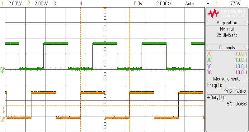
CH0 (orange) and CH1 (green)
The scope measured 202.6 Hz rather than 197 Hz. The PCA9685’s internal oscillator is nominally 25 MHz but not trimmed; it ran about 3% fast on this Click. Feed the chip an external clock if the frequency must be exact.
Do not write the registers while the kernel driver owns the chip. See Binding and Unbinding I²C Drivers.
Using the Kernel Driver and sysfs PWM
The kernel’s pwm-pca9685 driver makes the chip a standard Linux PWM
controller, which programs can use through /sys/class/pwm. Cargt kernels
do not include this driver. Add it as a module with a kernel configuration
fragment in your own layer (see Developing Applications and Kernel Modules):
recipes-kernel/linux/files/pca9685.cfg containing
CONFIG_PWM_PCA9685=m, and recipes-kernel/linux/linux-imx_%.bbappend:
FILESEXTRAPATHS:prepend := "${THISDIR}/files:"

SRC_URI += "file://pca9685.cfg"
The driver package, kernel-module-pwm-pca9685, must come from the same
kernel build as the kernel on the board.
The Click has no device tree node, so tell the kernel about the chip at run
time. The driver then loads, and a pwmchip appears with 17 channels: one
per output, and channel 16, which drives all of them at once:
root@imx91-cargt-00363-00365:~# echo pca9685 0x40 > /sys/bus/i2c/devices/i2c-1/new_device
root@imx91-cargt-00363-00365:~# dmesg | tail -1
[  438.151128] i2c i2c-1: new_device: Instantiated device pca9685 at 0x40
root@imx91-cargt-00363-00365:~# ls /sys/class/pwm/
pwmchip0
root@imx91-cargt-00363-00365:~# cat /sys/class/pwm/pwmchip0/npwm
17
Export a channel, then set its period and duty cycle in nanoseconds and enable it. This runs CH0 at 200 Hz with 25% duty:
cd /sys/class/pwm/pwmchip0
echo 0 > export
echo 5000000 > pwm0/period          # 5 ms = 200 Hz
echo 1250000 > pwm0/duty_cycle      # 1.25 ms = 25%
echo 1 > pwm0/enable
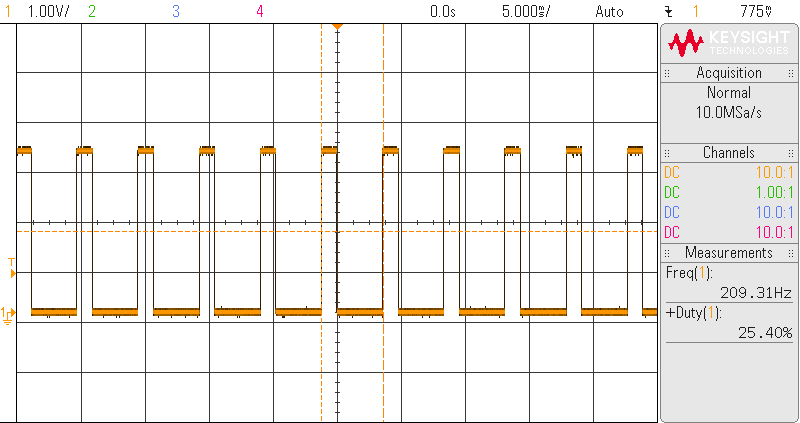
CH0 with duty_cycle 1250000
The prescaler cannot make exactly 5 ms. The driver picks the nearest period
it can, 4.915 ms, and keeps the duty cycle in nanoseconds, so 1.25 ms becomes
25.4% of the real period. With duty_cycle 3750000, the scope measured
76.3% rather than 75%:
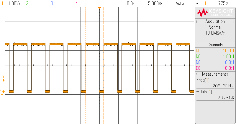
CH0 with duty_cycle 3750000
To get exact percentages, use a period the prescaler can make: 4096 × (prescaler + 1) × 40 ns, for example 4915200 for about 203 Hz.
All 16 channels share one period. The driver changes it only while no other
channel is exported, and otherwise keeps the old period even though
period reads back the new value. Set the period first, with only one
channel exported:
echo 0 > pwm0/enable
echo 655360 > pwm0/period           # the fastest: prescaler 3, nominally 1526 Hz
echo 327680 > pwm0/duty_cycle
echo 1 > pwm0/enable
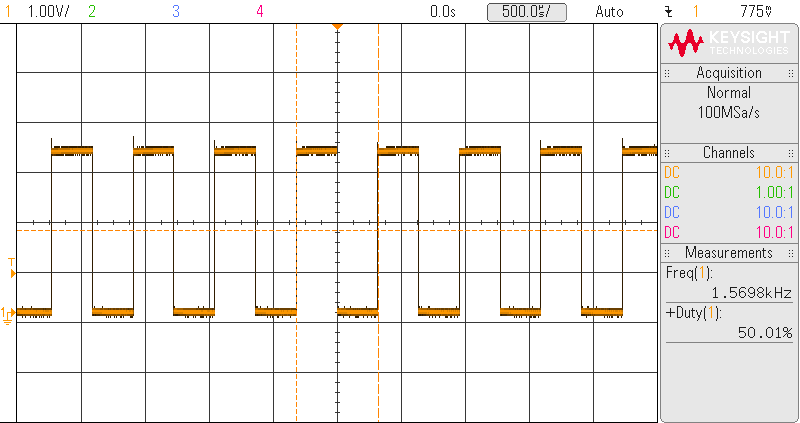
CH0 at the highest frequency
Nothing here survives a reboot: the PCA9685 starts asleep again, and the OE line is released. In a product, describe the chip in the device tree and set up the outputs in a startup service.
Binding and Unbinding I²C Drivers
Linux keeps I²C devices and their drivers in sysfs. Under
/sys/bus/i2c/devices, 1-0040 is the device at address 0x40 on
i2c-1. You can create and remove devices, and attach and detach their
drivers, at run time.
Create a device with new_device, giving the driver’s device name and
the address. The kernel then binds a matching driver if it has one. name
shows the device name, and the driver link shows which driver it is
bound to:
root@imx91-cargt-00363-00365:~# echo pca9685 0x40 > /sys/bus/i2c/devices/i2c-1/new_device
root@imx91-cargt-00363-00365:~# cat /sys/bus/i2c/devices/1-0040/name
pca9685
root@imx91-cargt-00363-00365:~# readlink /sys/bus/i2c/devices/1-0040/driver
../../../../../../../bus/i2c/drivers/pca9685-pwm
Unbind the driver to take the device away from it while keeping the
device. Do this before you use i2cset on a chip that a driver owns, or to
hand the chip to your own user-space code. The driver’s pwmchip
disappears, and the device no longer has a driver link:
root@imx91-cargt-00363-00365:~# echo 1-0040 > /sys/bus/i2c/drivers/pca9685-pwm/unbind
root@imx91-cargt-00363-00365:~# ls /sys/class/pwm/
root@imx91-cargt-00363-00365:~# ls /sys/bus/i2c/devices/1-0040/
modalias
name
power
subsystem
uevent
Bind it again to give the device back to the driver. The PCA9685 driver turns every output off and puts the chip to sleep when it binds, so register settings made while it was unbound are lost:
root@imx91-cargt-00363-00365:~# echo 1-0040 > /sys/bus/i2c/drivers/pca9685-pwm/bind
root@imx91-cargt-00363-00365:~# ls /sys/class/pwm/
pwmchip0
Remove the device with delete_device and the address. The driver is
unbound first; the PCA9685 driver puts the chip to sleep, so its outputs
stop:
root@imx91-cargt-00363-00365:~# echo 0x40 > /sys/bus/i2c/devices/i2c-1/delete_device
root@imx91-cargt-00363-00365:~# dmesg | tail -1
[  360.852800] i2c i2c-1: delete_device: Deleting device pca9685 at 0x40
new_device and delete_device work only for devices created that way.
Devices described in the device tree are created at boot; you can unbind and
bind their drivers, but not delete them. Use a device tree node for hardware
that is always fitted.
Serial Ports
Serial ports are device files in /dev. On i.MX, the SoC’s UARTs are
/dev/ttyLP*; the mikroBUS UART on the 00365 is /dev/ttyLP1. USB
serial adapters appear as /dev/ttyUSB* (FTDI and similar) or
/dev/ttyACM*.
The examples use an RS232 Click, which converts the mikroBUS UART to RS-232 levels on a DB9 connector. A USB-to-RS-232 adapter plugged into the board’s USB port is connected to it through a null-modem adapter, so whatever one port sends, the other receives.
Note
Most RS-232 devices, including the RS232 Click and typical USB adapters, are wired the same way (as DTE). Connecting two of them needs a null-modem cable or adapter, which crosses TX and RX. Without one, nothing arrives in either direction.
Set both ports to the same speed with stty. raw passes bytes through
unchanged, and -echo stops the port from echoing what it receives:
root@imx91-cargt-00363-00365:~# stty -F /dev/ttyLP1 115200 raw -echo
root@imx91-cargt-00363-00365:~# stty -F /dev/ttyUSB0 115200 raw -echo
root@imx91-cargt-00363-00365:~# stty -F /dev/ttyLP1
speed 115200 baud; line = 0;
min = 1; time = 0;
-brkint -icrnl -imaxbel
-opost
-isig -icanon -echo
Read one port in the background and write to the other:
cat /dev/ttyUSB0 &
echo "hello from ttyLP1" > /dev/ttyLP1     # cat prints: hello from ttyLP1
kill %1
For an interactive terminal, use microcom -s 115200 /dev/ttyLP1 (press
Ctrl+X to exit) or minicom.
If nothing arrives, /proc/tty/driver/fsl-lpuart shows how many bytes
each i.MX UART has sent and received. Here 1: is ttyLP1, after
sending 54 bytes and receiving 19:
root@imx91-cargt-00363-00365:~# cat /proc/tty/driver/fsl-lpuart
serinfo:1.0 driver revision:
0: uart:FSL_LPUART mmio:0x44380010 irq:17 tx:14880 rx:74 RTS|CTS|DTR|DSR|CD
1: uart:FSL_LPUART mmio:0x44390010 irq:18 tx:54 rx:19 CTS|DSR|CD
4: uart:FSL_LPUART mmio:0x42590010 irq:19 tx:2813 rx:908 RTS|CTS|DTR|DSR|CD
5: uart:FSL_LPUART mmio:0x425A0010 irq:20 tx:0 rx:0 CTS|DSR|CD
A tx count that grows while rx on the other end stays at 0 points to
the wiring, such as a missing null-modem adapter.
Hardware for the Examples
The examples use these Click boards in the 00365’s mikroBUS socket:
Relay 3 Click: two relays (GPIO outputs).
Opto 2 Click: four optocoupler inputs (GPIO inputs and the ADC).
PWM Click: an NXP PCA9685 16-channel PWM controller on I²C.
RS232 Click: an RS-232 transceiver for the mikroBUS UART.
mikroBUS Pins on the 00365
On the 00365, the mikroBUS logic signals go through level translators, which convert between the SOM’s 1.8 V signals and the socket’s 3.3 V. Apart from the I²C pins, the translators have a fixed direction, so each pin works in one direction only:
Pin |
Direction |
Linux |
Notes |
|---|---|---|---|
RST |
Output |
GPIO |
On the PCA9555 I/O expander, which has no interrupt line. |
CS |
Output |
GPIO |
SPI chip select (LPSPI8). A plain GPIO when SPI does not use it. |
SCK, MOSI |
Output |
LPSPI8 |
Not turned on in the default device tree. |
MISO |
Input |
LPSPI8 |
Not turned on in the default device tree. |
PWM |
Output |
TPM6 channel 1 |
Not turned on in the default device tree. |
INT |
Input |
GPIO |
Supports edge events. |
TX |
Output |
|
|
RX |
Input |
|
|
AN |
Analog input |
ADC channel 0 |
Through a buffer that scales the signal to the ADC’s 1.8 V range. |
SCL, SDA |
Both |
I²C |
Through a bidirectional translator. |
A Click board that drives a signal back on an output pin, such as RST or CS, is never seen by the SoC, and its driver fights the translator. Check which pins a Click board drives before you fit it.